Since I saw a several request for P16PRO40 strip board layout, so I decided to share it here.

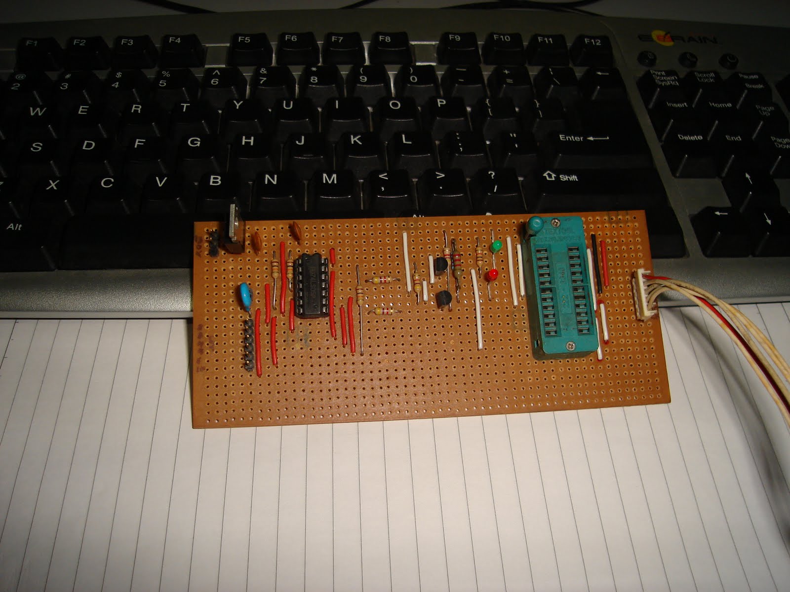
My PIC programming tool is a strip board based (AKA Veroboard). It is not as compact & neat as the commercial programmer but guess what, It took only 2 hours for me to built it from my electronic junkyard, except the 74LS05 and of course the strip board it self. Use normal IC socket if you don't have a ZIF socket.


I have made some modification to the circuit to match what I can find on my electronic junkyard. I replaced BC557 with A1015 (PNP), note that both transistor don't share the same pin layout. Just be careful if you want to use the alternative transistor.


On the power supply circuit, I've remove 7808 regulator since I already have 13V power supply. I only use 7805 to produce the 5V Vcc and the 13V Vpp comes directly from the main power supply.
I've also remove Vpp40 on/off from my PIC programmer. I've no plan to use them in the near future.
The programmer has been tested to work with 16F84A & 16F628A.
The recommended software for this programmer is WinPicProg 1.91 from http://www.winpicprog.co.uk/. It is simple but reliable software for PIC programming.

If you are using 74LS05 or 74LS06, set your 'hardware' setting as below. They are both HEX Inverter Open Collector output ICs but 74LS06 has extra features = with Buffer/Driver and 30V output.

Below is my test circuit, just a simple blinking program to test it out.


Additional images ...

Tidak ada komentar:
Posting Komentar